| HTS 101-03: One switch - eleven housing and cooling options | ||
 |
 |
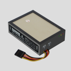 |
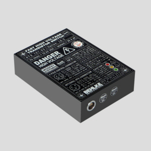
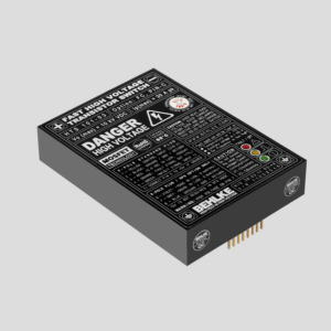
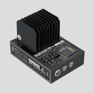
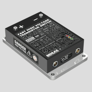
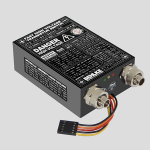
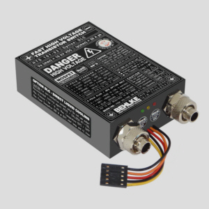
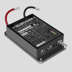
| 1) HTS 101-03 with shielded control input (LS-C) | 2) HTS 101-03 in flat case (FC) with pins (PIN-C) | 3) HTS 101-03 with ceramic cooling surface (CCS) |
 |
 |
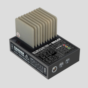 |
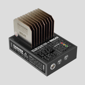
| 4) HTS 101-03 with nickel plated copper cooling fins (CF) | 5) HTS 101-03 with graphite cooling fins (CF-GRA) | 6) HTS 101-03 with ceramic cooling fins (CF-CER) |
 |
 |
 |
| 7) HTS 101-03 with potential-free Cu cooling flange (GCF) | 8) HTS 101-03 for indirect liquid cooling with water (ILC) | 9) HTS 101-03 for direct liquid cooling with Galden(DLC) |
 |
 |
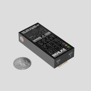 |
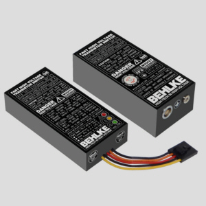
| 10) HTS 101-03 in pulser configuration (PC) | 11) HTS 101-03 with separated control unit (SEP-C) | 12) The HTS compact series for low power (HTS 121-01-C) |
|
1) HTS 101-03 with shielded
input (opt. LS-C). 1m linkage cable & 2nd socket is included. High quality self-latching
system (LEMO). Housing: Flame retardent and heat
resistant hard plastics. 2) HTS 101-03 in flat case (opt. FC) with soldering pins for control connection (opt. PIN-C). Dimension 89x64x17 mm. Flame retardent and heat resistant housing according to UL94-V0. 3) HTS 101-03 with ceramic cooling surface (opt. CCS). The top side of the switching module is made of ceramics to reduce thermal resistance to ambient. Forced convection recommended. 4) HTS 101-03 with nickel plated copper cooling fins (opt. CF). Available in various size, form and thickness (-X1, -X2, -XS, -LC, -1). Switches with option CF can also be immersed in oil tanks. 5) HTS 101-03 with graphite cooling fins (opt. CF-GRA). Compared to Cu, graphite has a similar cooling performance but only 20% of the weight. Please note the reduced heat capacity. 6) HTS 101-03 with option CF-CER (ceramic cooling fins). Ceramic cooling fins are potential free and can reduce the EMI in noise critical applications. We suggest forced convection. 7) HTS 101-03 with potential-free Cu cooling flange (opt.GCF) and high frequency switching option (opt. HFS). The flange can be mounted on heat sinks. For medium f(max) and Pd(max). 8) HTS 101-03 with indirect liquid cooling (opt. ILC). For mains water and other conductive coolants. The internal heat exchanger is made of ceramics. For medium f(max) and Pd(max). 9) HTS 101-03 with direct liquid cooling (opt. DLC). For non-conductive fluids (e.g. GALDEN HT-135 or low viscose oil). Best for high frequency applications with very high power dissipation. 10) HTS 101-03 in pulser configuration (opt. PC) with HV pigtails (option PT-HV), shielded input (LS-C ) and plastic flange housing (option FH). HV sockets and additional part components are integrated. The option PC can also be combined with the above cooling options. Please consult factory for more details. 11) HTS 101-03 with separated control control unit (option SEP-C). To place the control electronics up to 1m away from the power electronics. Plug connection with self-latching mini plug. 12) If it must be really small: The new HTS compact series. The picture shows the HTS 121-01-C (12 kV/15A) with option FC and PIN-C (flat case + pins for the input). Dim. 79x38x17 mm. |
||
| Options list for the high voltage switching module HTS 101-03: | |
|
Option (1) |
Description |
|
|
|
| MBC | Mechanical Backward Compatibility to the previous switch models. All connectors, dimensions and attachment identical with the "historical" switch models HTS 81, 51, 31 ff. |
|
HFB |
High Frequency Burst: Improved burst capability of driver. Improved recovery time for shorter pulse spacing and connectors for external driver buffer capacitors, so far required. |
|
HFS |
High Frequency Switching: External supply of auxiliary driver voltage (50-350 VDC according to type). Necessary if the specified “Max. Operating Frequency” shall be exceeded. (2) |
|
LP |
Low Pass: Low pass filter at the control input. Propagation delay time will be increased by ~50 ns. Jitter + 500 ps. Improved EMC, better noise immunity and less critical wiring. (3) |
| UFTR | Ultra Fast Thermotrigger: Advanced temperature protection for the high-voltage switch. Switch shut down within 5 seconds if Pd(max) is exceeded by 300% @ ΔT=25K (50 to 75°C) |
| UFTS | Ultra Fast Thermosensor: Temperature measurement directly on the power semiconductors by means of a special sensor with high electrical isolation and low thermal impedance. |
|
TT-C |
Customized Transition Time: Customized rise & fall times to meet individual design requirements. (2) |
|
MIN-ON |
Minimum On-Time: Individually increased Minimum On-Time to ensure a minimum on duration indepently of control signal. For safety relevant circuits. |
|
MIN-OFF |
Minimum Off-Time: Individually increased Minimum Off-Time to ensure a minimum off duration indepently of control signal. For safety relevant circuits. |
|
ST |
Stage Tapping: Connectors at the individual stages of stack in order to utilize single power semiconductors. To achieve fast rise times also at very low operating voltages (<0.01xVo). |
|
LL |
Low Leakage Current: Off-state current reduced to less than 10% of the specified value. Not available in connection with cooling fin options. |
|
LN |
Low Noise: Internal power driver modified for zero noise emission for a specific period of time. Relevant in conjunction with sensitive detector amplifiers (e.g. SEV/MCP) only. (2) |
|
ISO-25 |
25 kV Isolation: Isolation Voltage increased to 25 kVDC. Housing dimensions may change for some models. |
|
ISO-40 |
40 kV Isolation: Isolation Voltage increased to 40 kVDC. Housing dimensions may change for some models. Only in connection with option PT-HV or TH. |
|
ISO-80 |
80 kV Isolation: Isolation Voltage increased to 80 kVDC. Housing dimensions may change for some models. Only in connection with option PT-HV or TH. |
|
ISO-120 |
120 kV Isolation: Isolation Voltage increased to 120 kVDC. Housing dimensions may change for some models. Only in connection with option PT-HV or TH. |
| ISO-200 | 200 kV Isolation: Isolation Voltage increased to 200 kVDC. Housing dimensions may change for some models. Only in connection with option PT-HV or TH. |
|
I-PC |
Integrated Part Components: Integration of small part components according to customer’s specifications (e.g. capacitors, snubbers, damping resistors, diodes, opto couplers). (2) |
|
I-FWD |
Integrated Free-Wheeling Diode: Built-in parallel diode with short recovery time. In connection with inductive load only. |
|
I-FWDN |
Integrated Free-Wheeling Diode Network: Built-in parallel diode plus serial blocking diode with short recovery time. In connection with inductive load only. |
|
I-TS |
Integrated Thermo Sensor: Integrated temperature sensor for external temperature measurements according to customers specifications (NTC, KTY, PT-100 etc). |
|
LS-C |
Shielded Socket for Control Connection: Shielding for all inputs. Input impedance 100Ω. With 1m (3ft) linkage cable and 2nd socket. Improved noise immunity. (3)(4) |
|
PT-C |
Pigtail for Control Connection: Flexible leads (l=75 mm) with PCB connector (AMP-modu) instead of pins. Recommended for modules with options CF & GCF. |
|
PT-HV |
Pigtails for HV Connection: Flexible leads with cable lugs. For increased creepage. PT-HV is standard for all types with >25 kV switching voltage. Not for extremely fast circuits. |
|
SEP-C |
Separated Control Unit: Control unit with LED indicators in a separate housing (dim. 79x38x17 mm). Linkage cable (<1m) with plug. Control unit with soldering pins or pigtails. |
| FOI-I | Fibre Optics Input / Inhibit: Additional optical inhibit input to turn-off the switch by using the inhibit input with a fibre-optical signal (only in combination with option SEP-C) (2) |
|
FOI-C |
Fibre Optics Input / Control: Additional optical control input to trigger the switch with a fibre-optical signal (only in combination with option SEP-C) (2) |
| FOO-F | Fibre Optical Output / Fault: Additional optical output to read-out the failure condition with a fibre-optical signal (only in combination with option SEP-C) (2) |
| PC | Pulser Configuration: Switch combined with custom specific part components. Integrated in a plastic flange housing with hv connectors according to the customers specifications. (2) |
|
UL94 |
Flame Retardant Casting Resin: Casting resin according to UL-94-VO. Minimum order quantity required. (2) |
|
TH |
Tubular Housing: Tubular instead of rectangular housing. Adaption to specific ambient conditions or in case of difficult assembly situations. (2) |
|
FC |
Flat Case: Height of standard plastic housings reduced to 19 mm or less. Not in combination with cooling options CF, GCF and DLC. |
|
ITC |
Increased Thermal Conductivity: Special moulding process to increase the thermal conductivity of the module. Pd(max) will be increased by approx. 20-30%. (2) |
|
CF |
Non-Isolated Cooling Fins: Standard sizes in categories I to VII according to model. Nickel plated copper 0.5 mm, fin height 35 mm. For air and oil cooling. |
|
CF-1 |
Non-Isolated Cooling Fins d=1mm: Nickel plated copper 1.0 mm instead of 0.5 mm. The Max. Power Dissipation will be increased by ~80 %. For air and oil cooling. |
|
CF-X2 |
Non-Isolated Cooling Fins enlarged by x2: Fin area enlarged by factor 2. Not relevant in connection with liquid cooling. |
|
CF-CS |
Non-Isolated Cooling Fins with customized shape: Individual shape to meet specific OEM requirements. (2) |
|
CF-LC |
Non-isolated Cooling Fins optimized for liquid cooling: Double fins, nickel plated copper, 0.5 mm thickness, height 20 mm. |
| CF-HP | Cooling Fins, High Performance: Non-Isolation Cooling Fins with 200% cooling power, approx. 2mm spacing between fins, forced convection recommended |
|
CF-GRA |
Non-isolated Cooling Fins made of graphite: Very light weight compared to copper at similar heat transfer, but reduced heat capacity. 0.5 or 1 mm thickness, height 35 mm. |
|
CF-CER |
Isolated Cooling Fins made of ceramics: Heat transfer properties similar to alumina. Forced convection recommended, height 35 mm. |
|
CCS |
Ceramic Cooling Surface: Top side of switching module made of special ceramics. Heat transfer properties similar to alumina. 10 kVDC isolation. Forced convection recommended. |
|
C-DR |
Cooling for Driver: Extra cooling for the driver and control electronics. Recommended in combination with option HFS at higher switching frequencies. (2) |
|
GCF |
Grounded Cooling Flange: Nickel-plated copper flange for High Power applications. Max. isolation voltage 40kV. Increased coupling capacitance CC. |
|
ILC |
Indirect Liquid Cooling: Liquid cooling for all kind of conductive coolants incl. water. Internal heat exchanger made of ceramics. For medium power and medium frequencies. |
|
DLC |
Direct Liquid Cooling: Internal cooling channels arround the power semiconductors. The most efficient cooling for high frequency applications. For non-conductive coolants only. |
|
HI-REL |
High Reliability / MIL Versions: Available on request. (2) |
|
|
|
|
(1) New option code: Data sheets may differ from this coding system (especially older ones) and do not indicate all possible options as per above table.
(2) Please
consult factory for detailed information. |
|
|
|
|
|
Further information, data sheets and drawings are available on request. All data and specifications subject to change without notice. BEHLKE POWER ELECTRONICS 09-05-2014 |
|
| X | |
 |
|
|
|
|
